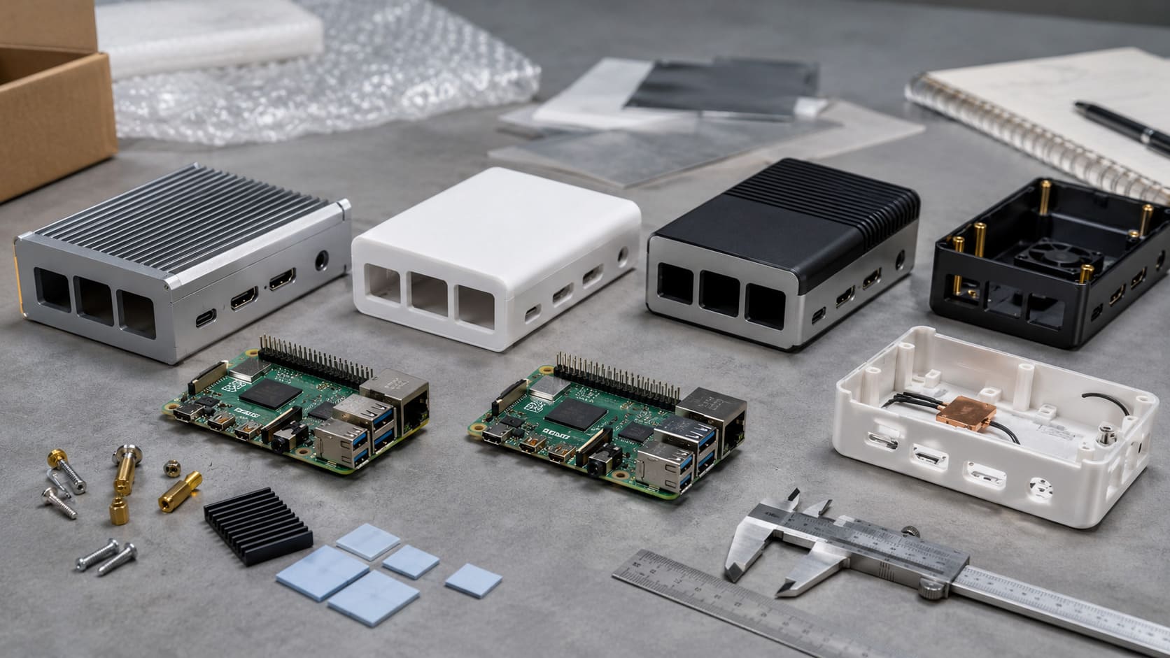
A lot of beginners do not get scared by code first. They get scared by the wires.
I have seen that many times. Someone buys a Raspberry Pi, opens a GPIO pinout image, and suddenly the whole thing stops feeling fun. The board looks small. The pins look close together. The labels look technical. Then the first question shows up: Where do I even start without breaking something?
I understand that feeling very well.
GPIO looks simple from far away. It is just a row of pins on a board. But once you try to connect a real LED, a button, or a sensor, the picture changes. Now you are dealing with voltage, current, pin numbering, software setup, and one quiet fear in the back of your mind: What if I wire this wrong and damage the Pi?
That fear is not silly. It is useful. It tells me a beginner is paying attention.
At the same time, I also think GPIO gets made to look harder than it really is. Many guides throw too much information at you too early. They show full pinout charts, technical terms, and long code blocks before they explain the simple logic behind what is happening. That is where many people lose confidence.
I do not want to teach GPIO that way.
In this guide, I want to slow the process down and make it feel human. I will walk through what GPIO really is, how the pins are laid out, what tools actually matter, how to wire a first circuit, how to control it with software, and how to avoid the mistakes that catch most beginners. I will also talk about safety, because confidence is good, but false confidence is expensive.
I learned this lesson in a very ordinary way. One time, I watched a beginner connect an LED directly to a pin without a resistor because the LED “lit up fine” in a quick test. It worked for a moment. That was the problem. Quick success can hide a bad habit. GPIO rewards careful thinking more than lucky moments.
That is why I think beginners need more than instructions. They need judgment.
So before we start pushing wires into a breadboard, we need to answer one basic question first: what GPIO actually is, and why those little pins matter so much.
What Is GPIO and Why Does It Matter?
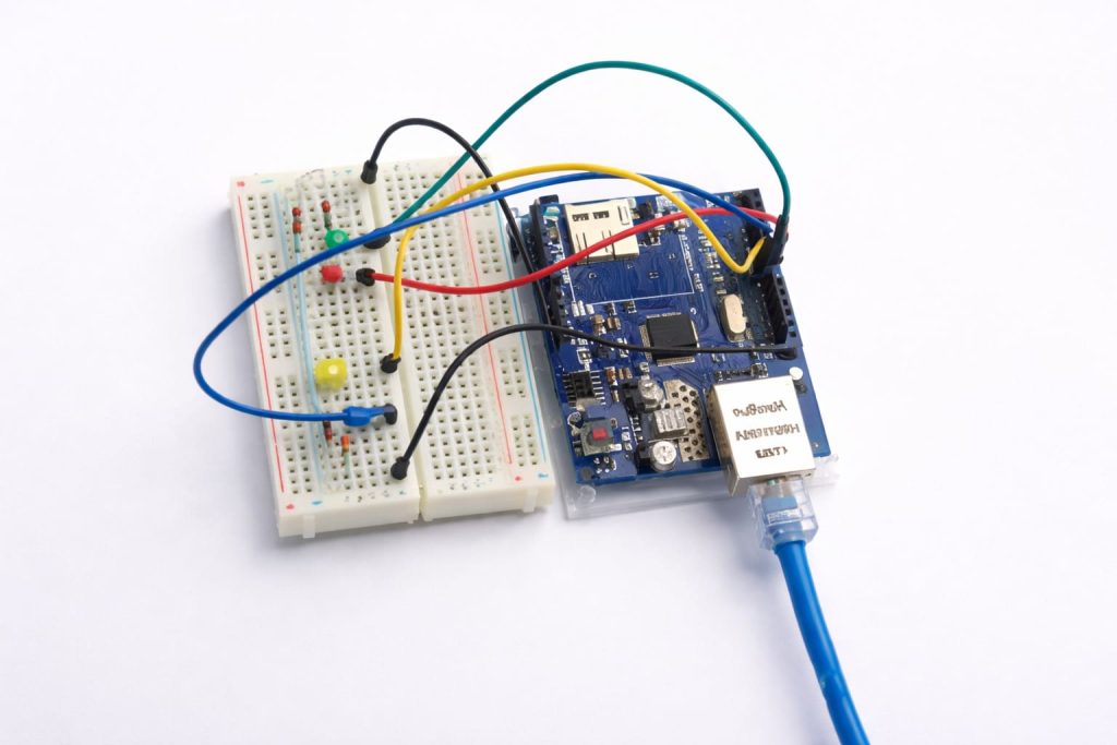
GPIO stands for General Purpose Input/Output. That sounds dry. I know. But the idea behind it is actually very simple.
These pins let the Raspberry Pi talk to the outside world.
That is the heart of it.
A Raspberry Pi on its own is a small computer. It can run software, store files, and connect to the internet. But GPIO is what lets it do something physical. GPIO lets the Pi turn an LED on. GPIO lets it read a button press. GPIO lets it get data from a temperature sensor. GPIO lets it control a relay, a motor driver, or a buzzer. Without GPIO, the Pi stays mostly inside the screen. With GPIO, it starts touching the real world.
What GPIO stands for and how it works
I like to think of GPIO as a set of little doors.
Some doors let signals go out. Some doors let signals come in.
When a GPIO pin is set as an output, the Pi sends a signal through that pin. That signal can tell another component to do something. For example:
- turn on an LED
- activate a relay
- send a pulse to a buzzer
- control a device step by step
When a GPIO pin is set as an input, the Pi listens. It waits for a signal from outside. For example:
- a button gets pressed
- a sensor changes state
- another module sends a digital signal
That simple input/output idea is the foundation of almost every beginner GPIO project.
| GPIO role | What it does | Simple example |
|---|---|---|
| Input | Receives a signal into the Pi | Reading a button |
| Output | Sends a signal out from the Pi | Lighting an LED |
Still, I think many beginners miss one important point here: a GPIO pin is not a power supply in the way many people imagine. It is a control point. That is a big difference. A beginner sometimes treats GPIO like a general-use power outlet. That is risky thinking.
How GPIO pins interact with the real world (input vs output)
The real world is messy. GPIO is precise.
That mismatch is where many problems begin.
Inside software, a pin may be described as HIGH or LOW. In real wiring, that usually means one of two states:
- HIGH = voltage present
- LOW = no voltage, or close to ground level
So when the Pi sends a HIGH signal to an LED circuit, the LED can turn on. When a button sends a HIGH signal into the Pi, the software can react.
It sounds clean. It is clean. But only if the wiring is clean too.
For example, a button is not “smart.” It does not know what the Pi expects. It only connects or disconnects part of a circuit. So the way you wire that button decides what the Pi sees. That is why input wiring needs thought, not guessing.
Most beginners start with the same four kinds of things, and I think that is smart.
LEDs
LEDs teach output. They are simple, visible, and satisfying. You write code, and a light turns on. That feedback matters.
Buttons
Buttons teach input. They help you understand how the Pi listens for changes.
Sensors
Sensors make the project feel more alive. A sensor can let the Pi react to temperature, distance, light, or motion.
Relays
Relays let a low-power GPIO signal control a bigger device indirectly. This is where projects start feeling practical, but this is also where safety matters much more.
| Component | GPIO type | Why beginners use it |
|---|---|---|
| LED | Output | Easy first test |
| Button | Input | Clear interaction |
| Sensor | Input | Real-world data |
| Relay | Output/control | Controls larger loads |
I think that is why GPIO matters so much. It is not just a technical feature. It is the point where code stops being abstract and starts becoming physical.
And once that starts making sense, the next challenge appears fast: the pin layout itself. Because even if you understand the idea of GPIO, the board still has to be read correctly.
Understanding the GPIO Pin Layout
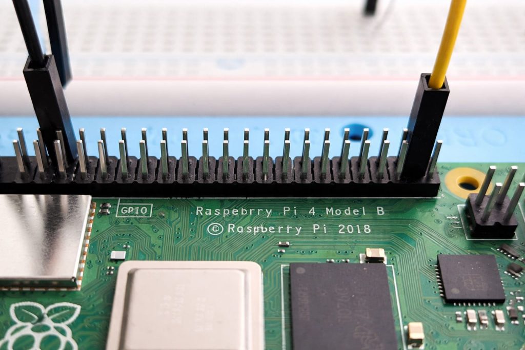
This is where many beginners pause and stare at the screen.
The first time I looked at a Raspberry Pi pinout chart, I did not think, “This is elegant.” I thought, “Why are there so many labels for such a small row of pins?” That reaction is normal.
GPIO pin layout is not difficult because it is advanced. It is difficult because several systems are shown at once.
Physical pin numbering vs BCM numbering
This is one of the most common beginner mistakes.
A Raspberry Pi GPIO header has physical pin numbers. These are the actual positions on the board. Pin 1 is in one location. Pin 2 is next to it. This numbering is about where the pin is physically placed.
Then there is BCM numbering. This is the numbering used by the Broadcom chip inside the Pi. This numbering is about which GPIO signal you are controlling in software.
That means physical pin 11 can be BCM GPIO17.
That is not a small detail. That is exactly the kind of mismatch that causes confusion.
| Numbering type | Meaning | Example |
|---|---|---|
| Physical | The pin’s position on the header | Pin 11 |
| BCM | The chip’s GPIO channel number | GPIO17 |
When a tutorial says “connect to GPIO17,” it usually means BCM numbering. When someone shows you a diagram with rows of 1, 2, 3, 4, that often refers to physical pins.
I always tell beginners to check this first before doing anything else. One wrong assumption here can make a correct circuit seem broken.
Power pins (3.3V, 5V) and ground pins explained
Not all header pins are GPIO pins.
Some pins provide power. Some are ground. Some are for communication. That is why reading the header casually can cause trouble.
The main power-related pins beginners need to notice are:
- 3.3V pins
- 5V pins
- GND pins
The GPIO logic on Raspberry Pi uses 3.3V. That matters a lot. It means most GPIO signals should stay in that logic range.
Ground pins are just as important. They complete the circuit. A circuit without shared ground often behaves strangely, or not at all.
| Pin type | Purpose | Beginner note |
|---|---|---|
| 3.3V | Low-voltage power supply | Safe logic reference for GPIO |
| 5V | Higher voltage power supply | Use carefully |
| GND | Ground connection | Needed to complete circuits |
A lot of beginners look for the “signal pin” and ignore the ground. I think that happens because ground feels passive. But a missing ground is one of the most active causes of failure.
Special function pins (I2C, SPI, UART)
Some GPIO pins can do more than basic input and output.
They may also support communication protocols like:
- I2C
- SPI
- UART
These let the Pi talk to displays, sensors, microcontrollers, and many other modules in a more structured way.
At beginner stage, I do not think you need to master all of that at once. But you should know these pins exist, because sometimes a pin is “general purpose” in one project and “special function” in another.
That can be useful. It can also become confusing if a guide assumes you already know which mode the pin is using.
How to read a GPIO pinout diagram correctly
The best way to read a pinout diagram is slowly, and with a question in mind.
Do not try to memorize the whole thing.
Ask:
- Which physical pin am I using?
- Is it power, ground, or GPIO?
- If it is GPIO, what is its BCM number?
- Does the tutorial use physical numbering or BCM numbering?
That small checklist prevents a lot of mistakes.
I also think beginners do better when they use a printed pinout chart or keep one open beside the project. Memory is helpful. Reference is better.
| Question to ask | Why it matters |
|---|---|
| Is this a GPIO pin or a power pin? | Prevents wrong wiring |
| Am I using physical or BCM numbering? | Prevents software mismatch |
| Does this pin have a special function? | Avoids communication conflicts |
Once the pin layout starts making sense, the next question becomes practical: what do I actually need on my desk to start wiring safely without turning this into a shopping mistake?
Essential Tools and Components You Need
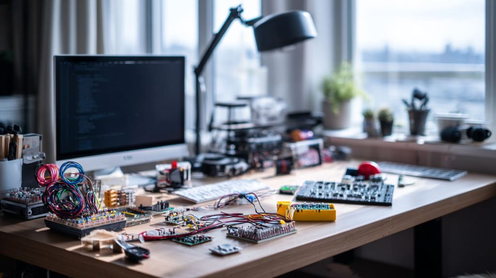
I have seen beginners make two opposite mistakes here.
One beginner buys almost nothing and tries to learn with random loose parts. Another beginner buys a giant electronics kit full of things they do not understand. Both paths can slow learning down.
I think the best start is a small, useful set of tools that teaches the basics clearly.
Basic tools (breadboard, jumper wires, resistors)
If I had to build a beginner GPIO desk from scratch, I would start with a few simple things.
Breadboard
A breadboard lets you build circuits without soldering. That matters because beginners will change wiring often. They should. GPIO learning is full of small corrections.
Jumper wires
These connect components to the Pi and the breadboard. Male-to-male jumper wires are usually the first type people use.
Resistors
These look small and boring. They are not boring. They protect parts of the circuit by limiting current. They are one of the first habits that separate careful beginners from careless ones.
| Tool | Why it matters | My view |
|---|---|---|
| Breadboard | Easy testing without soldering | Best place to make beginner mistakes safely |
| Jumper wires | Quick connections | Buy decent ones, bad wires waste time |
| Resistors | Current control and protection | Essential, not optional |
A resistor kit is cheap. Replacing damaged parts is more annoying. That trade-off is easy.
A beginner does not need a huge component box at first. A few parts can teach a lot.
LEDs
These are perfect for first output tests.
These teach digital input clearly.
Simple sensors
A temperature or motion sensor can make a project feel more interesting without becoming too complex.
I usually think beginners learn better when each part has one clear lesson.
| Component | Main lesson |
|---|---|
| LED | Output control |
| Button | Input reading |
| Sensor | Real-world interaction |
Optional tools for better workflow (multimeter, GPIO breakout board)
These are not mandatory on day one, but they become valuable very fast.
Multimeter
A multimeter helps check voltage, continuity, and wiring mistakes. It saves time. More importantly, it helps you stop guessing.
GPIO breakout board
This plugs into the GPIO header and maps pins more clearly to a breadboard. It makes the layout easier to read, especially for beginners.
I think a breakout board is underrated. It reduces mental friction. And beginner projects have enough friction already.
Choosing safe and reliable components
Cheap parts are fine. Unclear parts are not.
I would rather use a simple LED from a basic kit than use a mystery sensor board with poor labeling and no documentation. A beginner needs parts that make learning clearer, not parts that create new confusion.
Here is how I judge beginner components:
- clear labels
- simple documentation
- common voltage compatibility
- widely used in tutorials
- stable connection quality
| Good beginner choice | Risky beginner choice |
|---|---|
| Standard LED kit | Random unlabeled LED bag |
| Common push button | Unknown switch module |
| Basic sensor with docs | No-name board with vague pin labels |
A beginner project does not fail only because of bad thinking. Sometimes it fails because a weak wire or confusing module adds noise to the process.
And once the desk is ready, a more serious topic shows up. It is not the most exciting topic, but it is the one that saves the most regret: GPIO safety.
GPIO Safety Basics (Very Important)

This section is not glamorous. It is still one of the most valuable parts of the whole guide.
I have noticed that beginners usually worry about code errors more than wiring errors. That makes sense, because code looks harder. But in GPIO work, a small wiring mistake can matter more than a small code mistake.
Wrong code often gives you no result. Wrong wiring can give you damage.
Why 3.3V logic matters (and what can go wrong)
Raspberry Pi GPIO uses 3.3V logic.
That means the GPIO pins are designed to work with signals at that level. If a beginner sends 5V directly into a GPIO input pin, that can damage the board.
This is one of those facts that sounds simple but gets ignored because many electronic modules also mention 5V somewhere on the label. That creates false confidence.
I think this is where beginners need a stronger habit: never assume voltage compatibility just because a part powers on.
| Signal level | Meaning for Raspberry Pi GPIO |
|---|---|
| 3.3V | Normal logic level |
| 5V direct to GPIO input | Dangerous |
A device may use 5V for power and still use 3.3V-safe logic. Or it may not. The only safe path is to check.
Avoiding short circuits and overcurrent
A short circuit happens when electricity takes an unintended low-resistance path. In beginner work, that can happen because of:
- misplaced jumper wires
- wrong breadboard rows
- accidental pin bridging
- loose metal touching the board
Overcurrent happens when too much current flows through a component or pin.
Both problems can become expensive fast.
I do not say that to scare beginners. I say it because calm caution is part of learning electronics. The goal is not to feel nervous. The goal is to stop treating wiring like guesswork.
When and how to use resistors
A resistor limits current. That sounds like a technical line from a textbook. In practice, it means the resistor helps prevent your LED or pin from getting more current than it should.
For a beginner LED circuit, a resistor is not a “nice extra.” It is part of the correct design.
| Component setup | Better practice |
|---|---|
| GPIO to LED directly | No |
| GPIO to resistor to LED | Yes |
That first setup may appear to work for a moment. That is exactly why it fools people.
I have learned to distrust circuits that “seem okay” but skip basic protection. Temporary success can be the most misleading teacher in electronics.
Protecting your Raspberry Pi from damage
Here are the safety habits I think matter most:
- power off before changing wiring
- double-check pin numbers before connecting
- confirm voltage levels on sensors and modules
- use resistors where needed
- never force wires into unclear positions
- use a multimeter when unsure
I would rather move slowly through one safe circuit than race through three sloppy ones.
| Safety habit | Why it helps |
|---|---|
| Power off before rewiring | Prevents accidental shorts |
| Check numbering system | Prevents wrong pin use |
| Confirm voltage | Protects GPIO inputs |
| Use resistors | Limits current safely |
Once these ideas are clear, the whole process becomes less stressful. And that makes the first real circuit much more enjoyable.
So now the fun part starts. Let’s wire something simple that actually works.
How to Wire Your First Circuit (Step-by-Step)
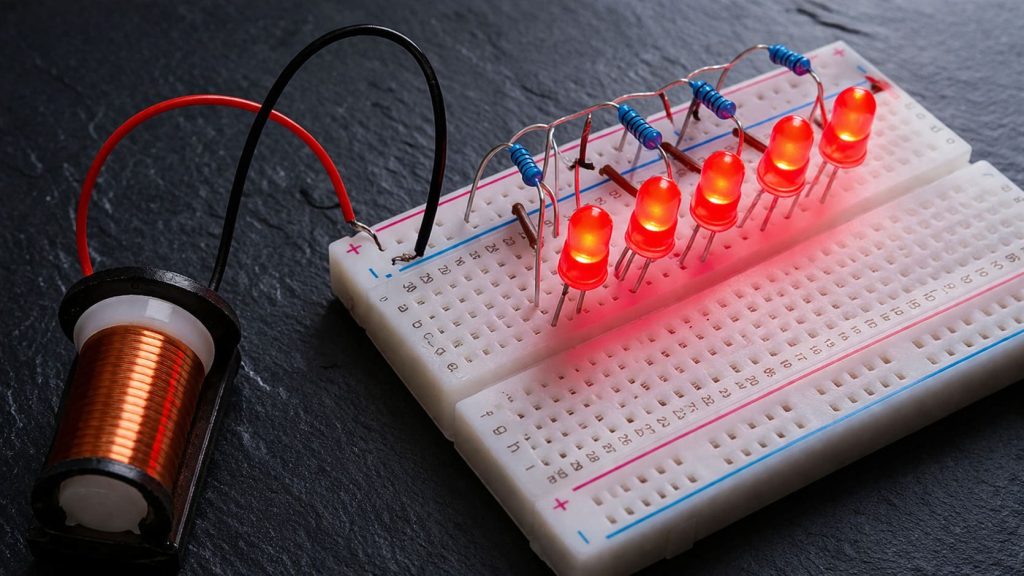
I always think the first circuit should feel small and satisfying.
Not ambitious. Not clever. Just clear.
That is why the LED circuit is still one of the best starting points. It teaches output, current flow, resistor use, ground connection, and software control all at once.
Understanding a simple LED circuit
An LED circuit for Raspberry Pi usually includes:
- one GPIO output pin
- one resistor
- one LED
- one ground connection
The logic is simple. The GPIO pin sends a signal. Current flows through the resistor and LED. Then it returns to ground. The LED lights up.
That is the whole story.
But that simple story contains a lot of beginner lessons.
Connecting GPIO → resistor → LED → ground
A typical beginner setup works like this:
- Connect a GPIO output pin to one side of a resistor.
- Connect the other side of the resistor to the long leg of the LED.
- Connect the short leg of the LED to a ground pin.
That order matters.
The resistor can usually go on either side of the LED in the circuit path, but it must be in series with the LED.
| Connection part | Purpose |
|---|---|
| GPIO pin | Sends output signal |
| Resistor | Limits current |
| LED | Produces visible light |
| Ground | Completes the circuit |
A practical thought before wiring
I always recommend checking the LED legs first. The longer leg is usually the positive side. The shorter leg usually goes toward ground. A beginner often flips the LED once or twice. That is normal. It does not mean the whole project is broken.
Visualizing current flow in a circuit
This is where many beginners improve fast.
Do not only memorize the layout. Ask where the current goes.
I think of the circuit as a loop:
GPIO output → resistor → LED → ground
That mental picture helps with debugging later too. If the LED does not light, I ask: where is the loop broken?
- wrong GPIO pin?
- missing ground?
- LED reversed?
- resistor in wrong row?
- code not turning the pin on?
That way of thinking is better than random rewiring.
Common wiring mistakes beginners make
I have seen these mistakes again and again:
- using the wrong pin because of BCM vs physical confusion
- placing both LED legs in the same breadboard row
- forgetting the ground connection
- reversing the LED
- connecting without a resistor
| Mistake | Result |
|---|---|
| Wrong numbering system | Circuit does not match code |
| Missing ground | No complete circuit |
| LED reversed | No light |
| No resistor | Risk of damage |
| Wrong breadboard row | Broken path |
A first circuit teaches more than success. It teaches how to look at physical connections carefully. That habit becomes even more useful once software gets involved.
Because a wired circuit alone does nothing. The Pi still needs instructions.
How to Control GPIO with Software

This is the part many beginners expect to be hardest.
Strangely, it is often easier than the wiring.
A wire does not explain itself. Code usually does.
Using Python for GPIO control (RPi.GPIO / gpiozero)
Python is one of the easiest ways to control GPIO on Raspberry Pi. Two common libraries beginners see are:
- RPi.GPIO
- gpiozero
I think gpiozero feels friendlier for beginners. It hides some complexity. RPi.GPIO is also useful because many older tutorials use it.
| Library | Beginner experience | My view |
|---|---|---|
| gpiozero | Easier and cleaner | Great first choice |
| RPi.GPIO | More manual setup | Good for learning fundamentals |
Both can work. What matters more is understanding what the code is asking the pin to do.
Setting up pins as input or output
Before using a GPIO pin in code, you usually define its role.
If the pin will turn an LED on, it is an output.
If the pin will read a button, it is an input.
This is important because the Pi needs to know whether it should speak or listen through that pin.
That simple distinction is one of the core ideas in GPIO work. I come back to it often because many confusing projects become clearer once I ask, “Is this pin supposed to send or receive?”
Writing your first script to blink an LED
A blinking LED script is almost a tradition in Raspberry Pi learning, and I think that is fine. Traditions survive because they work.
The script usually does this:
- selects a pin
- sets it as output
- turns it on
- waits
- turns it off
- repeats
The value of this project is not the blinking itself. The value is that it proves three things at once:
- your wiring works
- your pin selection works
- your code works
That is a great beginner checkpoint.
Running and testing your code
When the LED blinks, beginners feel relief. I understand that. The Pi is no longer abstract. It is responding.
But I think this is also a good moment for critical thinking.
If the LED blinks, ask:
- Did I choose the correct numbering mode?
- Does my code match the real wire location?
- Is the delay doing what I expect?
- Could I explain why it works, not just repeat it?
That last question matters.
Real learning starts when a beginner can explain the circuit and code in simple language. Not perfectly. Just honestly.
| Test result | What it suggests |
|---|---|
| LED blinks | Wiring and output code likely correct |
| LED stays off | Check power path, pin choice, and code |
| LED stays on | Check logic and loop behavior |
Once output makes sense, the next step feels more interactive. Now the Pi stops just sending signals and starts reacting to them.
Reading Input from GPIO (Buttons & Sensors)

Output is satisfying. Input is where projects start feeling alive.
The first time I wired a button and saw the Pi react to a press, it felt less like programming and more like building a conversation between hardware and software.
How input pins work (HIGH vs LOW signals)
An input pin reads signal state.
Usually, that means it reads whether the signal is HIGH or LOW.
For beginners, I think the key thing to understand is that an input pin should not be left in a vague state. If it floats, the reading can become unstable and confusing.
That is why input design needs a little more care than people expect.
This topic sounds harder than it is.
A button can connect a pin to either voltage or ground, but the pin needs a stable default state when the button is not being pressed. That is where pull-up and pull-down logic comes in.
- Pull-up: default state is HIGH
- Pull-down: default state is LOW
The button press changes that state.
| Method | Default state | Button changes it to |
|---|---|---|
| Pull-up | HIGH | LOW |
| Pull-down | LOW | HIGH |
I think beginners often copy button wiring without understanding this idea. Then when the button behaves strangely, the problem feels mysterious. It is usually not mysterious. It is just an undefined default state.
A button press is not always one clean signal.
Mechanical buttons can “bounce.” That means one physical press may create several tiny rapid signal changes. Software may read that as multiple presses.
This is one of those details that surprises beginners because human motion feels smooth. Electronics do not always see it that way.
Debouncing can be handled in hardware or software. For beginners, software debouncing is often enough.
The deeper lesson here is useful: the real world is noisy. GPIO projects become better when we respect that noise instead of pretending it is not there.
Reading sensor data through GPIO
Sensors add another layer of thinking.
A simple digital sensor may act much like a button. It sends a HIGH or LOW signal depending on what it detects. Other sensors use more advanced communication methods, but many beginner sensors still start with simple pin logic.
When reading sensors, I usually ask these questions first:
- what voltage does it use?
- is the output digital or analog?
- does it need pull-up or pull-down support?
- does it require a special protocol like I2C?
| Sensor question | Why it matters |
|---|---|
| Voltage level? | Prevents damage |
| Digital or analog? | Affects compatibility |
| Output type? | Affects code and wiring |
| Needs protocol? | Changes pin setup |
A button teaches control. A sensor teaches interpretation. The Pi is no longer just waiting for a press. It is watching a condition.
And once that starts working, many beginners want more. More devices. More loads. More practical projects. That is exactly when caution needs to grow too.
Expanding Your Projects Safely
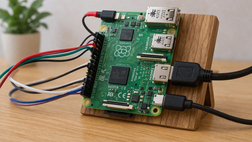
This is the stage where beginner excitement can become risky.
The first LED works. The button works. Then someone says, “What if I control a lamp, a pump, or several modules at once?” That jump is exciting. It is also where project stakes rise.
Using relays to control higher voltage devices
A Raspberry Pi GPIO pin should not directly drive high-voltage devices. That is what relays are for.
A relay lets a low-power GPIO signal control a separate higher-power circuit. In simple words, the Pi tells the relay what to do, and the relay handles the switching.
That does not make the whole project automatically safe. It just creates the right separation.
I think beginners need to hear this clearly: a relay is not magic protection. It is a tool. Safe relay use still depends on good wiring, correct ratings, and respect for the load being controlled.
Connecting multiple components at once
A project gets more complex fast when multiple components are added.
Now you may have:
- several GPIO pins in use
- shared ground connections
- mixed power needs
- more crowded breadboards
- more chances for wiring confusion
That is why I like labeling circuits early. Even simple notes can help:
- which wire goes to which pin
- which module uses 3.3V
- which device uses external power
- where ground is shared
I have seen many beginners lose time not because the project was too advanced, but because the desk became visually chaotic.
Power considerations for larger projects
This is where critical thinking matters a lot.
A Raspberry Pi can control many things, but it cannot safely power everything from its GPIO pins. A component may need more current than a GPIO pin should provide.
That means a beginner must separate two questions:
- Can the Pi signal this device?
- Can the Pi power this device?
Those are not the same question.
| Question | Why it matters |
|---|---|
| Can GPIO control it? | Logic compatibility |
| Can GPIO power it? | Current and safety limits |
That distinction prevents many bad assumptions.
When to use external power supplies
Use an external power supply when the device draws more power than the Pi should provide directly, or when the project includes motors, relays, strips, or modules with higher current demands.
In those cases, the Pi often provides the control signal, while the external supply provides the actual power.
Still, grounds often need to be referenced properly together depending on the setup. This is where beginners should slow down and read carefully before wiring.
I know that caution can feel less exciting than experimentation. But in electronics, careful scaling is part of real progress.
And before expanding too far, it helps to stop and look at the mistakes that catch beginners over and over again.
Common Beginner Mistakes and How to Avoid Them
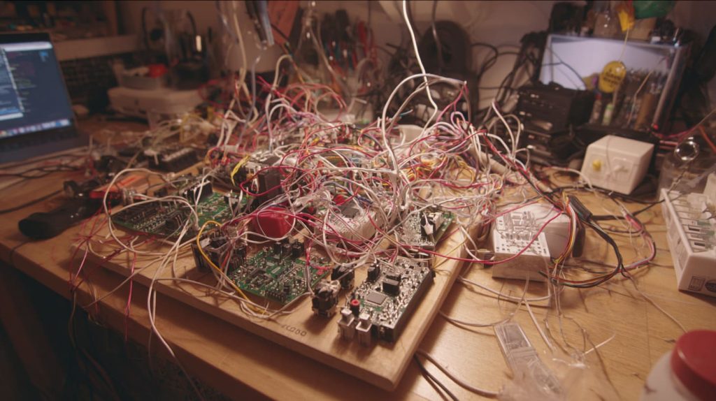
I do not think beginners fail because they are careless people. Most of the time, they fail because the early details look too small to matter.
Then the small detail turns out to be the whole problem.
Mixing up pin numbering systems
This is still near the top of the list.
A beginner follows a wiring diagram using physical pin numbers, then writes code using BCM numbering without realizing the difference. Now the code looks fine. The wiring looks fine. The project still fails.
That kind of error is frustrating because everything seems almost correct.
The fix is simple:
- decide which numbering scheme your project uses
- keep that choice consistent
- check the tutorial language carefully
Forgetting resistors (and damaging components)
This happens because beginners want quick proof that the circuit works.
I understand that. But skipping a resistor is one of those shortcuts that teaches the wrong lesson.
A circuit that lights up without proper current control is not “working well.” It is just getting away with something for a moment.
Wiring errors on breadboards
Breadboards look friendly, but they can trick beginners.
People often assume every nearby hole is connected. It is not. Breadboard rows and rails follow specific internal patterns.
I always recommend that beginners stop and map the breadboard mentally before assuming a connection exists.
| Breadboard mistake | Real issue |
|---|---|
| Wrong row use | No connection where expected |
| Broken power rail assumption | Power not shared as expected |
| Crowded layout | Harder to debug |
Ignoring grounding issues
Ground feels invisible. That is exactly why it gets ignored.
A missing or incorrect ground reference can make a perfectly good module act dead or unstable. I have seen beginners replace code, replace wires, and even replace components before noticing the ground problem.
That kind of experience teaches humility fast.
| Common mistake | Best fix |
|---|---|
| Wrong numbering system | Use one numbering method consistently |
| No resistor | Add proper current limiting |
| Breadboard confusion | Trace each row carefully |
| Missing ground | Confirm complete return path |
When a beginner starts seeing these patterns, progress gets faster. Not because mistakes stop happening, but because mistakes start becoming easier to identify.
That leads naturally into a skill that feels advanced, but should really begin early: debugging.
Debugging GPIO Circuits Like a Pro
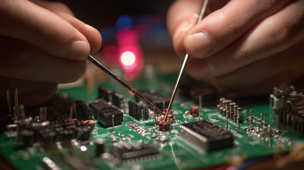
Debugging sounds like something experts do. I do not see it that way.
I think debugging is just careful observation with better habits.
A beginner who learns to debug early becomes much stronger than a beginner who only copies projects that happen to work.
How to check wiring step by step
When a circuit fails, I do not change five things at once. I check one thing at a time.
My basic order looks like this:
- check the power is off before touching wires
- confirm the pin number in the guide
- confirm the pin number in the code
- trace the wire path physically
- check LED direction or button position
- confirm ground connection
- power on and test again
That slow method feels less exciting. It works better.
Using a multimeter for troubleshooting
A multimeter is one of the best tools a beginner can add.
It helps answer real questions, such as:
- is voltage present here?
- is this connection continuous?
- is the power rail actually live?
- is ground where I think it is?
That changes troubleshooting from guessing into checking.
| Multimeter use | What it helps confirm |
|---|---|
| Voltage check | Signal or supply presence |
| Continuity test | Physical path connection |
| Ground reference | Shared return path |
Identifying software vs hardware issues
This is one of the most useful debugging questions:
Is the problem in the code, or in the wiring?
A good way to test this is to isolate the system.
- If the wiring looks right, try a very simple known-good script.
- If the code looks right, test the hardware path with a simpler setup.
- If the LED still does not blink, reduce the circuit.
- If a button acts strangely, test the pin state directly.
The point is not to be clever. The point is to remove variables.
Simple debugging workflow for beginners
I like simple workflows because panic makes people skip steps.
Here is the beginner version I trust most:
| Step | Question |
|---|---|
| 1 | Is the correct pin being used? |
| 2 | Does code match the chosen numbering system? |
| 3 | Is the circuit path complete? |
| 4 | Is voltage safe and present where expected? |
| 5 | Is the component orientation correct? |
| 6 | Can I simplify the circuit and test again? |
I think that is what “debugging like a pro” really means. Not speed. Not fancy tools. Just calm method.
And once you can build, test, and debug small projects reliably, the next thought arrives almost by itself: How do I move beyond the breadboard stage?
Taking It to the Next Level
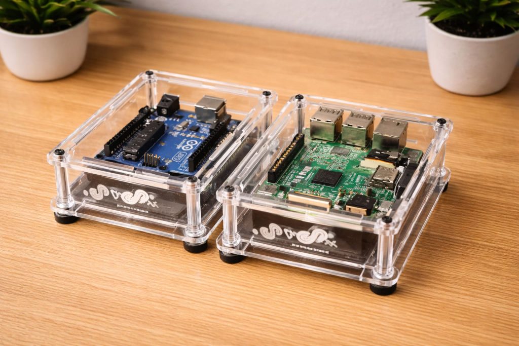
There is a point where a breadboard stops feeling like a playground and starts feeling temporary.
That is usually a good sign.
It means the project is becoming real.
Moving from breadboard to custom PCB or enclosure
A breadboard is great for testing ideas. It is not always great for long-term use.
Wires can loosen. Layouts can become messy. Transport can break connections. That is why many projects eventually move toward a PCB, a more fixed wiring design, or a proper enclosure.
I think this transition matters more than many beginners expect. A working prototype is one thing. A stable product is another.
| Stage | Main benefit | Main weakness |
|---|---|---|
| Breadboard | Fast testing | Loose and temporary |
| PCB / fixed wiring | Stable and repeatable | Less flexible |
| Enclosed build | Better protection | Needs planning |
Using HATs and expansion boards
HATs and expansion boards make it easier to add features without designing everything from scratch.
They can help with:
- motor control
- displays
- sensors
- power handling
- communication functions
I think they are very useful, but beginners should still ask one important question: Am I learning the function, or only plugging in a shortcut?
Both are fine at different times. But it helps to know which one you are doing.
Integrating GPIO into real products
This is where a hobby project starts becoming a practical build.
A GPIO-based design may be used in:
- automation systems
- monitoring devices
- test fixtures
- branded kits
- education products
- custom ODM projects
In those cases, the questions change. It is no longer only about “Does it work?” It becomes:
- Does it stay stable?
- Is it easy to assemble?
- Is it safe for users?
- Can it be repeated at scale?
- Can it fit cleanly into a case?
That shift from experiment to product is one I see often in business work.
Designing for stability and long-term use
Long-term use asks for boring but important thinking:
- cable strain relief
- heat management
- mounting points
- access to ports
- protection from dust or accidental contact
- clean internal layout
I think good product design often looks obvious only after someone has done the hard thinking quietly.
And that leads to a detail many beginners ignore at first, but later realize matters a lot: the case.
Choosing the Right Raspberry Pi Case for GPIO Projects
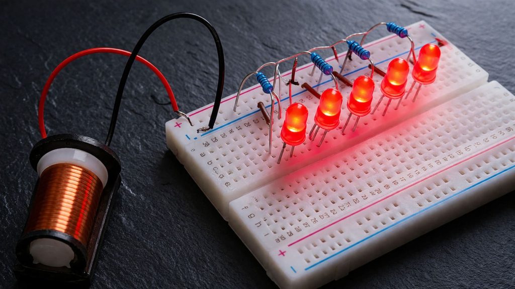
A case can look like an accessory. In GPIO work, it often becomes part of the design.
I say that because I have seen projects work well on a desk and then become awkward the moment someone tries to house them properly.
Why enclosure design matters for wiring projects
A GPIO project needs space, access, and protection.
A case that looks nice but blocks the GPIO header can slow down development. A case with poor airflow can make heat harder to manage. A case with no mounting logic can turn a clean board into a loose assembly.
That is why I do not see the case as the last cosmetic step. I see it as part of the working structure.
Features to look for (GPIO access, ventilation, mounting)
For GPIO-focused work, I usually look for these things:
- clear GPIO header access
- room for jumper routing
- ventilation if the Pi gets warm
- stable mounting points
- cutouts for needed ports
- enough internal height if modules are stacked
| Case feature | Why it matters |
|---|---|
| GPIO access | Easier wiring and testing |
| Ventilation | Better thermal control |
| Mounting points | More stable assembly |
| Port cutouts | Better usability |
| Internal space | Supports add-ons and wires |
A beginner may think, “I will solve the case later.” That can work for learning. It works less well for product use.
Custom cases for branding and project deployment
This is where my own work experience comes in very naturally.
Many buyers do not only want a Pi case. They want a case that fits a project, supports their hardware layout, and carries their brand. That can mean:
- custom logo printing
- engraved branding
- modified cutouts
- new internal support points
- retail packaging support
- different materials or finishes
For re-brand users and project buyers, the case becomes part of the value they offer to their own customers.
I have seen that especially with businesses selling through Amazon, local retail, or project-based channels. The board may be standard. The presentation and usability are not.
OEM/ODM considerations for scaling projects
Once a GPIO project moves toward scale, I think buyers should ask bigger questions:
- Can this layout be assembled repeatedly?
- Is the case easy to modify for project needs?
- Can the logo or label be added cleanly?
- Will the enclosure support future revisions?
- Is the supplier fast and detail-focused enough for real production?
These questions matter for people like Jacky or Davide, but also for creative ODM buyers who want to redesign a case around a different board or a special function.
| OEM/ODM factor | Why buyers should care |
|---|---|
| Custom cutouts | Better project fit |
| Logo / label support | Better brand identity |
| Fast production | Better stock planning |
| Design flexibility | Better product adaptation |
| Stable quality control | Fewer downstream problems |
I think a good case does more than protect the board. It protects the project logic around the board.
And after all of that, the best place to end is not with more complexity. It is with a clear reminder of what beginners really need to remember.
Conclusion
GPIO feels bigger than it is when you first look at it.
I think that is the most honest place to start. The pinout looks crowded. The wires feel risky. The terms sound technical. A beginner can easily assume this is only for people with an electronics background. I do not believe that is true.
What I have seen again and again is much simpler: beginners do well when they learn GPIO in the right order.
First, understand what the pins do.
Then, learn the layout.
Then, use the right basic tools.
Then, respect voltage and safety.
Then, wire one small circuit well.
Then, connect that circuit to simple code.
Then, test, break, fix, and learn.
That sequence matters.
A lot of frustration comes from trying to jump too far ahead. Someone wants to build a complex sensor system before they feel comfortable blinking an LED. Someone wants to control relays before they fully understand input and output. That path usually creates more confusion than progress.
I think starting small is not a sign of being inexperienced. It is a sign of building correctly.
If I had to reduce this whole guide to a few practical lessons, they would be these:
- learn the difference between physical and BCM numbering
- respect 3.3V GPIO logic
- use resistors where they belong
- never ignore ground connections
- debug slowly and one step at a time
- keep early projects simple enough to understand fully
Those habits will carry much further than one lucky project ever will.
And if your GPIO project is starting to move beyond testing and into real use, the mechanical side begins to matter too. A clean case, proper GPIO access, stable mounting, and custom enclosure design can make the difference between a desk prototype and a product that feels ready for market.
If you are building a Raspberry Pi project and need a custom case, branded enclosure, or OEM/ODM support for deployment, I would be glad to talk through it with you. You can reach me through Raspberrypicase.com and see whether we can help turn your GPIO build into something more stable, usable, and ready for the next step.