Skip to content

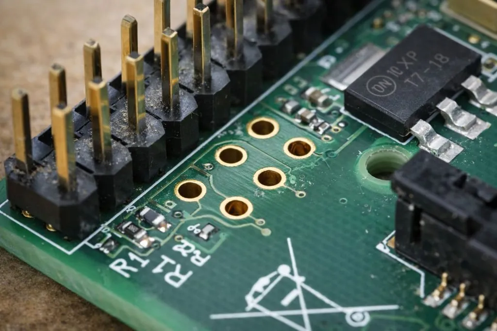
On many calls with buyers, I see the same moment. We are talking about cases, heatsinks, power supplies… and then someone says very casually, “We just use some GPIO pins to control the stuff.” That “some GPIO pins” often decides if the whole project feels solid or fragile after it reaches real users.
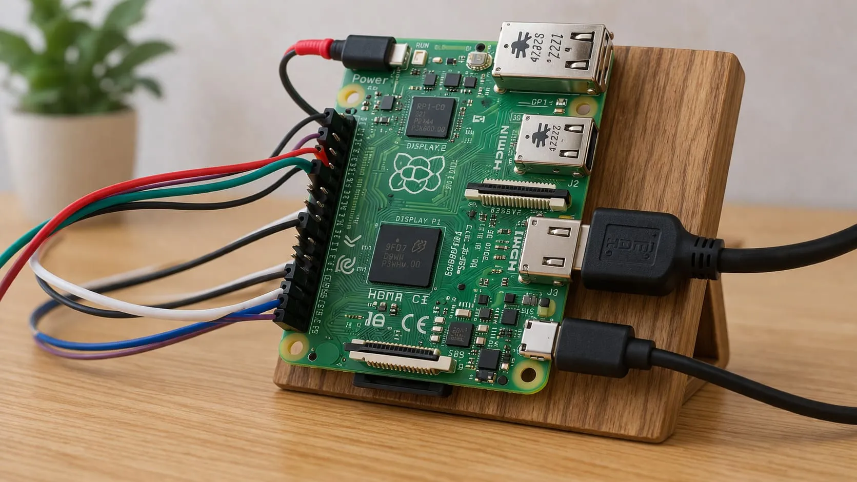
GPIO on a Raspberry Pi is the set of small metal pins that let the board talk to the physical world. They can read buttons, turn on LEDs, read sensors, drive relays, and speak to other chips. Without them, a Raspberry Pi is just a small computer. With them, it becomes a real control brain.
I care a lot about GPIO because I sit in the middle. On one side, I see people like Jacky in Belgium or Davide who want to sell Raspberry Pi kits and custom cases with their own brand. On the other side, I see factory people who worry about cables, clearances, heat and long-term stability. GPIO is the bridge between these two worlds.
In this article, I want to walk through what GPIO is, how it works, and how I use it in real projects. I will not only repeat textbook rules. I will share how I think when a customer says “we use two pins for a fan, one for a relay, maybe one for a button” and expects everything to just work.
One thing I learned from many painful projects: when I decide how to use GPIO on a Raspberry Pi, I am not choosing pins, I am choosing how much risk and future flexibility the buyer will have to live with.
What Is GPIO on the Raspberry Pi
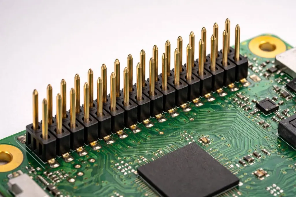
When I first show a Raspberry Pi board to a new customer, their eyes usually go to the USB or HDMI ports. My eyes go straight to the 40-pin header. That header is where all the quiet decisions live.
Definition of GPIO
GPIO means General Purpose Input/Output. On the Raspberry Pi, these are the pins that you can control from software. You can set them to “input” to read a signal from the outside world, or “output” to send a signal out.
A few simple examples:
- Read if a button is pressed
- Turn an LED on or off
- Detect if a door is open or closed
- Send a control signal to a relay module
GPIO is not tied to only one use. That is why it is “general purpose”. This is what makes the Pi so flexible, but it is also what creates confusion. One pin can be a simple digital output in one project and an I²C bus line in another. Same metal, different job.
Pinout Structure and Numbering
The 40-pin header looks like two neat rows, but there are two main numbering systems:
- Physical pin number (1–40, counted along the header)
- BCM (Broadcom) GPIO number (like GPIO2, GPIO3, etc.)
Most libraries and tutorials use BCM numbers, but some diagrams, forums, or old code use physical numbers. This is one of the first places where errors start.
A very simple comparison:
| View Type | Example Name | What It Means |
|---|---|---|
| Physical numbering | Pin 3 | Third metal pin from the corner |
| BCM numbering | GPIO2 | Actual internal GPIO name in the chip |
Some pins are not GPIO at all. They are:
- 3.3 V power
- 5 V power
- Ground (GND)
Some pins are used by default for special roles, like I²C for system functions. You can change many of these, but if you do it blindly, you may break basic things like your camera or HAT detection.
Voltage Levels and Electrical Characteristics
On Raspberry Pi boards, the standard GPIO logic level is 3.3 V, not 5 V. This matters more than many new users think.
- Logic HIGH: around 3.3 V
- Logic LOW: around 0 V
- Max current per pin: small (often designed for around 16 mA or less, and a total limit across all pins)
A short table to keep it clear:
| Item | Typical Value |
|---|---|
| Logic voltage | 3.3 V |
| Max per-pin current | ~16 mA (safe side) |
| Total current over GPIO | ~50 mA range |
| 5 V allowed on GPIO pin? | No |
This is where many cheap projects die. Some modules from the market send 5 V signals, or draw too much current, and the Pi’s GPIO gets damaged slowly or suddenly.
From my side as a supplier, when a buyer tells me they want to bring a 5 V sensor directly to the GPIO, I already see the RMA emails and angry Amazon reviews coming later.
To judge if a GPIO plan is realistic, I first look at voltage and current demands before I even care about how “cool” the feature sounds.
When people understand what GPIO really is on the Pi, it becomes much easier to design a good case, cable set, and accessory kit around it without constant surprises.
Understanding GPIO Functions
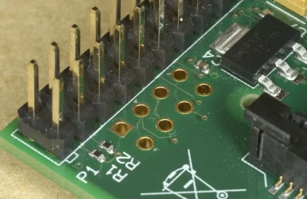
Once we know what the pins are, the next question is simple: what can they actually do? This looks obvious, but in real work the details decide if a device feels stable or “glitchy”.
Input vs Output Modes
Every GPIO pin can usually run in at least two simple modes:
- Input: read a signal from outside
- Output: send a signal out
As an input, the pin only measures if the voltage is closer to 0 V or 3.3 V (or somewhere between, which is a noisy zone you want to avoid). You use input for things like:
- Push buttons
- Switches
- Motion sensor outputs
- “Fault” or “ready” signals from other boards
As an output, the pin sets the level:
- Turn LEDs on and off
- Drive the input of a relay board
- Enable or disable another module
In code, changing direction is usually one line. In hardware, changing it later can mean redesigning the whole interface.
Pull-up/Pull-down Resistors
If you connect a GPIO pin as input but do not give it a clear reference, it floats. A floating pin can read as HIGH one second and LOW the next, just from noise. That creates random behavior.
To avoid this, we use pull-up or pull-down resistors:
- Pull-up: keeps the pin at HIGH when nothing is pressed
- Pull-down: keeps the pin at LOW when nothing is pressed
Example setup for a button:
| State | Button | Pull Type | GPIO Reads |
|---|---|---|---|
| Idle | Open | Pull-up | HIGH |
| Pressed | Closed | Pull-up | LOW |
| Idle | Open | Pull-down | LOW |
| Pressed | Closed | Pull-down | HIGH |
The Raspberry Pi can enable internal pull-ups and pull-downs in software. You can also add external resistors if needed. This small choice changes how stable your readings are and how resistant the system is to noise.
Alternate Pin Functions
Some GPIO pins can do more than simple HIGH or LOW. They can act as:
- I²C communication lines
- SPI communication lines
- UART TX/RX
- PWM outputs
- Other special functions depending on the model
On the pinout, you often see something like “GPIO18 / PCM_CLK / PWM0”. These are the alternate functions. You cannot use all functions at the same time; you must choose.
This is where planning matters. If a buyer wants I²S audio, hardware PWM for a fan, and SPI sensors, I look very carefully at the pinout to avoid conflicts.
Safe Usage and Electrical Limits
Safety for GPIO means three things:
- Voltage: stay at 3.3 V for logic pins
- Current: stay inside per-pin and total limits
- Protection: avoid shorts, spikes, and ESD
Some basic rules I always push to customers:
- Use a transistor, MOSFET, or driver chip to control motors or large relays
- Never feed 5 V directly into a GPIO pin
- Use level shifters when talking to 5 V devices
- Use resistors with LEDs to limit current
A quick checklist table:
| Risk Type | Simple Protection |
|---|---|
| Over-voltage | Level shifter, resistor divider |
| Over-current | Driver IC, transistor, series resistor |
| ESD | TVS diodes, careful connector design |
| Shorts | Fuse, polyfuse, good case layout |
The biggest real-world mistake I see with GPIO functions is not choosing the wrong mode; it is underestimating how rough real users are with cables, power, and connectors once the device leaves the lab.
When I review a GPIO plan for a new case or kit, I usually think less about “what is possible” and more about “what will still work when a tired technician plugs things in the wrong way at 2 a.m.”.
When the core functions of GPIO are clear, the communication features start to make much more sense, and that is where many interesting projects begin.
Communication Interfaces via GPIO
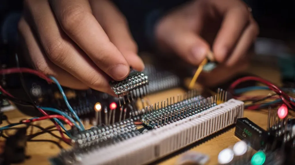
GPIO is not only about simple on/off signals. A lot of power comes from using the pins as communication lines to other chips and boards.
I2C (Inter-Integrated Circuit)
I²C is a two-wire communication bus:
- SDA: data line
- SCL: clock line
You can connect several devices on the same two wires, each with its own address. Common I²C devices:
- Temperature and humidity sensors
- Real-time clocks
- IO expanders
- Small displays
A simple I²C thinking pattern:
| Question | Design Impact |
|---|---|
| How many devices on the bus? | Address conflict risk |
| Cable length? | Noise and signal integrity |
| Voltage level? | Need for level shifter or not |
If a buyer wants to ship a kit with many I²C sensors on long cables, I already expect to discuss pull-up resistors and cable quality.
SPI (Serial Peripheral Interface)
SPI is a faster bus with more wires:
- SCLK: clock
- MOSI: master out, slave in
- MISO: master in, slave out
- CS / CE: chip select lines
It is very good for:
- High-speed ADCs
- Displays
- Some flash storage chips
SPI is not as friendly for sharing one bus with many devices unless you manage CS lines carefully. That means more pins, more routing, and more chance to make a small wiring mistake.
UART (Universal Asynchronous Receiver/Transmitter)
UART is the classic serial port:
- TX: transmit
- RX: receive
This is good for:
- Debugging consoles
- Linking the Pi with another microcontroller
- Talking to many modules that still use serial protocol
On Raspberry Pi, the main UART pins can double as the default serial console. If you use them for your own device, you may need to adjust system settings.
I see many projects where someone starts by plugging a USB-TTL adapter to the UART pins “just for debugging” and then decides to ship the product like that. That can be OK, but it should be a choice, not an accident.
PCM / I2S / PWM
Some GPIO pins can carry audio and timing signals:
- I²S / PCM: digital audio to DACs or audio codecs
- PWM: pulse-width modulation for fan control, dimming LEDs, servo control, etc.
These are very powerful, but they lock certain pins into special roles. Once you use I²S on those pins, you cannot treat them like simple on/off lines.
A small summary:
| Interface | Main Use | Key Trade-off |
|---|---|---|
| I²C | Many slow sensors | Address conflicts, pull-ups needed |
| SPI | Fast peripherals | More pins, more routing |
| UART | Simple serial | Limited number of ports |
| I²S/PCM | Audio | Fixed pin usage |
| PWM | Precise control | Limited true hardware channels |
When I help a customer choose interfaces over GPIO, the real question in my head is not “what works today”, but “which protocol will still be flexible when they want to add one more sensor or LED strip in the next version”.
Once the communication roles are clear, the next step is simple: we need to control all of this from code in a clean way.
Programming GPIO on Raspberry Pi
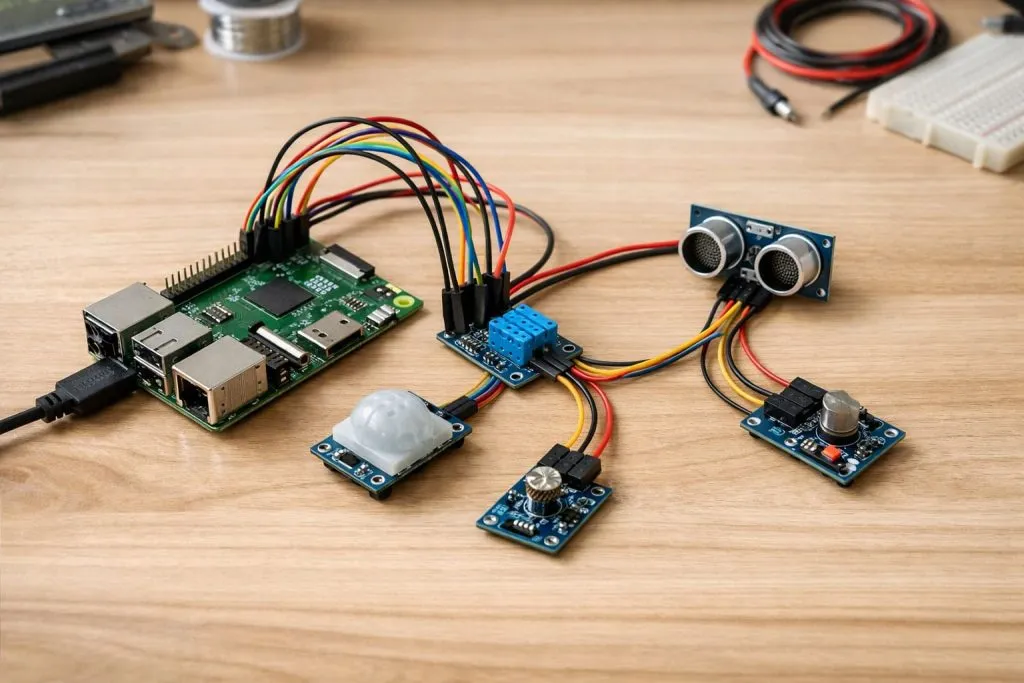
Many engineers who buy from us are strong in software and feel less comfortable with hardware. For them, GPIO becomes real only when they see code.
GPIO Libraries and Tools (e.g. RPi.GPIO, gpiozero)
The good news is that you do not need to touch raw registers. On Raspberry Pi, we often use:
- RPi.GPIO (classic, low-level style)
- gpiozero (higher-level, very friendly)
There are also command-line tools and other libraries, but these two cover most use cases for Python.
A quick comparison:
| Library | Style | Good For |
|---|---|---|
| RPi.GPIO | Lower level | People who want direct control |
| gpiozero | Object-oriented | Fast prototyping, teaching, testing |
If a client tells me they want to sell a beginner kit with GPIO projects, I often suggest we design the examples with gpiozero first, then add RPi.GPIO versions for advanced users.
Programming Languages (Python, C, Node.js)
Most people start with Python because:
- It is easy to read
- Many examples online use it
- Libraries are well supported
But you can also use:
- C / C++ for higher performance or tighter timing
- Node.js for JavaScript people
- Other languages that wrap the underlying GPIO access
I do not try to push any one language as “the best”. I care more about whether the code is simple and stable enough that other team members can maintain it later.
Basic Input Reading Example
A typical input example is a button on a GPIO pin:
- Configure the pin as input
- Enable pull-up or pull-down
- Read its value in a loop or with events
Simple pseudo-flow:
set pin as input
set internal pull-up
while running:
read pin state
if state changed:
do something
People often try to read the pin too fast, or ignore bouncing, and then think the hardware is “bad” because they see double presses. Many times the fix is in the software logic, not the wiring.
Basic Output Control Example
For output, the classic example is an LED:
Configure the pin as output
Set HIGH to turn on, LOW to turn off
Add a delay between changes
Pseudo-flow:
set pin as output
loop forever:
set pin HIGH
wait
set pin LOW
wait
Even this simple example hides design decisions: do you use a resistor? what value? is the LED on the Pi, on a small board, or on a long cable in a metal case?
When I look at GPIO code from a buyer, the first thing I wonder is not “which language is this?” but “what will happen if this loop runs for three years in a hot cabinet with real people pressing buttons in strange ways”.
Once programming feels natural, people start asking, “What can I actually build with this?” and that is where things become fun.
Common GPIO Applications and Projects

In real orders, I keep seeing the same families of GPIO applications. They look simple, but they can be very different in quality depending on small design choices.
LED Control Projects
Controlling LEDs is usually the first step:
Power indicators
Status LEDs for Wi-Fi, error, running state
Simple progress or mode feedback
Typical design pattern:
| Use Case | LED Behavior |
|---|---|
| Power on | Solid green |
| Error | Slow red blinking |
| Updating firmware | Fast blinking |
| User activity | Short flash on each event |
This looks like decoration, but in field devices these small lights are how technicians “talk” to the box without opening it or connecting a laptop.
Push Button Input and Signal Reading
Buttons and switches are everywhere:
Start / stop
Reset
Mode change
Confirm actions
Good button design includes:
Pull-ups or pull-downs
Debounce logic in software
Clear human feedback (click feel, LED, or sound)
I once worked on a small control box where the only problem was a noisy button signal over a long cable. The electronics were perfect, but the cheap long cable turned a simple press into random signals. Replacing the cable and improving debounce fixed everything.
Sensor Integration (Temperature, Motion, etc.)
GPIO lets the Pi read many kinds of sensors:
Digital temperature sensors
PIR motion sensors
Reed switches on doors
Simple distance sensors
A small view:
| Sensor Type | Typical Interface | Typical Use |
|---|---|---|
| Digital temp | One-wire / I²C | Environment monitoring |
| PIR motion | Digital GPIO | Security / lighting |
| Reed switch | Digital GPIO | Door / hatch detection |
Here, the trade-off is often between cheap modules and industrial reliability. Some hobby modules are fine for a home lab but fail too fast in a factory or outdoor box.
Servo and Motor Control
With GPIO, and often with extra driver boards, you can control:
Servo motors (e.g. pan/tilt cameras)
DC motors (fans, pumps)
Stepper motors (small positioning tasks)
This usually involves:
PWM signals
Motor driver ICs or modules
Separate power rails and grounding schemes
This is where mechanical design meets electrical design. A motor that runs fine on a desk can cause big noise and brown-outs when placed inside a tight plastic case with weak airflow.
Home Automation Projects
Many people use Raspberry Pi as a small hub:
Turn lights on/off
Read door and window sensors
Control relays for pumps or heaters
Connect to cloud dashboards
GPIO is often linked to relay boards, contact input modules, or RF modules. The Pi becomes the “brain” in a bigger system.
Robotics and Control Systems
In robotics projects, GPIO might connect to:
Motor drivers
Encoders
Limit switches
IMU or other sensors via I²C or SPI
Here, timing and reliability matter a lot. A missed limit switch signal can break hardware. A noisy encoder reader can ruin motion control.
For all these common applications, the question I keep in my mind is how the project will behave after months of dust, heat, and human misuse, not just how nice it looks in the first demo.
Once people feel confident with these standard uses, some of them want to push GPIO further, and that leads into more advanced territory.
Advanced GPIO Applications
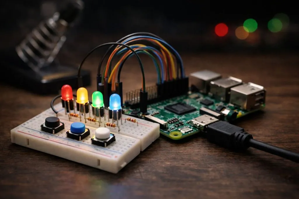
After the basic LED and button phase, GPIO can handle more subtle and powerful tasks. This is where careful thinking pays off.
PWM for Analog-like Control
PWM (Pulse-Width Modulation) lets us simulate “analog” control with digital pins. The pin switches between HIGH and LOW very fast. By changing the duty cycle, we change the average power.
Uses:
Control fan speed
Dim LEDs
Set servo positions
Simple PWM view:
| Duty Cycle | Perceived Result |
|---|---|
| 0% | Off |
| 25% | Low speed / brightness |
| 50% | Medium |
| 100% | Full on |
Hardware PWM channels are limited, so you must choose which loads really need smooth control and which can live with simple on/off.
Timing and Event Detection
GPIO can also detect:
Rising edges (LOW to HIGH)
Falling edges (HIGH to LOW)
Both edges
This is useful for:
Counting pulses
Detecting short events
Reacting quickly to changes
Good event design thinks about:
Debouncing
Minimum pulse width
Interrupt vs polling strategies
Using GPIO for Communication Protocols
Sometimes people implement protocols directly on GPIO with software (“bit-banging”). This can work, but:
It uses more CPU
It is more sensitive to OS timing
It may break under heavy load
I see this when a project starts small and then grows. At first, a bit-banged protocol is fine. Later, when more services run on the Pi, the timing becomes unstable. At that stage, switching to hardware-assisted interfaces is painful because the PCB and connectors are already fixed.
Interfacing with External ADC/DAC
Because Raspberry Pi does not have built-in analog inputs, many projects use:
External ADCs (analog-to-digital converters) via SPI or I²C
External DACs (digital-to-analog converters) for voltage output
This opens the door for:
Reading voltage, current, sensor signals
Generating control voltages
A small example table:
| Component Type | Typical Interface | Use Case |
|---|---|---|
| 12-bit ADC | SPI | Current/voltage measurement |
| 16-bit ADC | I²C | Precision sensors |
| DAC | SPI/I²C | Control of external equipment |
The tricky part with these advanced applications is not the first prototype; it is long-term drift, noise, and calibration once the device is in the field.
When I look at advanced GPIO usage in a customer design, I try to imagine how easy it will be for them to debug strange, “rare” errors one year after launch when project documentation is buried and half the team has changed.
After you decide how far you want to go with GPIO features, the next big question is how to keep things safe, stable, and easy to assemble.
Practical Tips and Best Practices
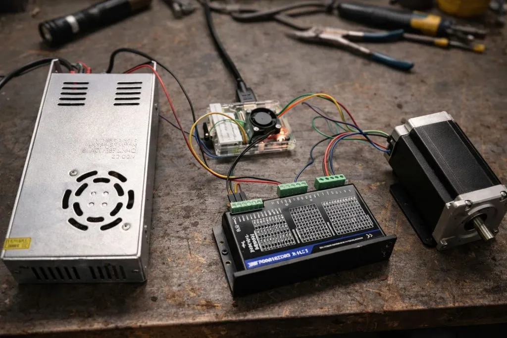
Over the years, I have collected many small rules that save time and money. They are simple, but they often decide whether a batch of products goes smoothly or becomes a headache.
Protecting Your Pi’s GPIO Pins
Some basic protection ideas:
Use series resistors on sensitive inputs
Use driver chips or MOSFETs for loads
Add diodes for inductive loads like relays and motors
Consider ESD protection on external connectors
Basic protection table:
| Risk | Suggested Protection |
|---|---|
| Static shock | TVS diodes, ESD-rated connectors |
| Over-current | Fuses, current-limiting resistors |
| Reverse | Diodes, keyed connectors |
Level Shifting and Power Considerations
Because the Pi’s GPIO is 3.3 V, any 5 V device needs attention:
Use level shifter modules
For slow signals, resistor dividers can be enough
Always share a common ground
Power planning questions:
How much current do my external modules draw?
Does the 5 V rail come from Pi or a separate supply?
What happens when one supply turns on before the other?
Breadboard and Wiring Tips
Prototyping is where many “hidden” problems are born:
Keep wires short where possible
Twist pairs for noisy signals or long runs
Label cables early (future you will say thank you)
Use color coding for power, ground, and signals
A simple wiring checklist:
| Item | Good Practice |
|---|---|
| Ground | One clear reference point |
| Power lines | Thicker wires, short runs |
| Signal lines | Away from power switching paths |
| Connectors | Locked or keyed where possible |
Debugging Common GPIO Issues
Common real-world GPIO problems:
Pin numbers mixed up (BCM vs physical)
Missing or wrong pull-ups/pull-downs
Loose ground connections
Power supply sag when loads switch on
My usual debug order is:
Check power supply and ground.
Confirm pin mapping and mode.
Use a simple script to test one pin at a time.
Swap cables or modules to see if the problem moves.
The best GPIO advice I can give is simple: never assume a problem is only in software or only in hardware; the bug is very often in the relationship between the two.
Once you have good habits, you can move faster and feel safe exploring new libraries, tools, and example designs from the community.
Tools, Resources and Libraries
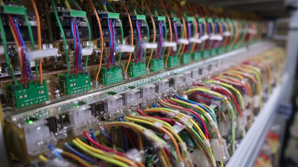
No one builds good GPIO projects alone. Good tools and references save a lot of trial and error, especially when you are preparing products for customers instead of personal hobby builds.
Pinout Reference Tools
Online pinout diagrams are my constant friends:
Graphical pinout sites with overlays
Printable PDFs for lab walls
Interactive tools where you can click a pin and see possible roles
Good pinout tools show:
BCM numbers
Physical numbers
Alternate functions
Power and ground pins
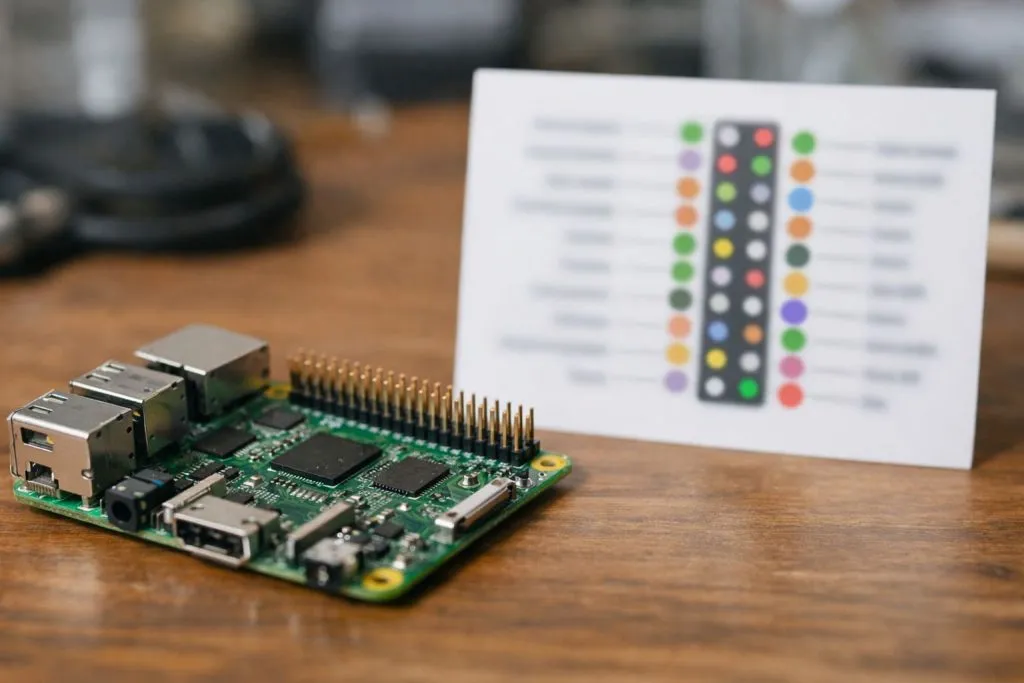
I often suggest that buyers print the pinout and include a small version inside the technical manual or even on the inside of the enclosure lid.
Official Raspberry Pi Documentation
The official Raspberry Pi documentation:
Describes electrical limits
Lists interface details
Shows configuration options for I²C, SPI, UART, etc.
Even if you usually learn from blogs or videos, checking the official docs at least once per project is a good habit. It helps catch small details that are easy to miss in community posts.
Community Tutorials and Example Repositories
The community is one of the biggest strengths of Raspberry Pi:
Step-by-step GPIO tutorials
Example code in Git repositories
Forum threads solving real problems
A simple way I work:
| Step | Action |
|---|---|
| Early idea | Search for similar project examples |
| Before final design | Check at least two independent sources |
| Before big production run | Run stress tests based on examples |
I do not treat online examples as perfect. I treat them as starting points and then adjust them to fit the reality of my customer’s use case, budget, and risk level.
When I pick resources for customers to follow, I try to imagine what will happen at 1 a.m. when something does not work and they copy-paste the first solution from a search result.
At the end of the day, tools and tutorials are there to support one bigger thing: clear thinking about what we actually want the GPIO system to do in our product.
Conclusion
When I look back at all the Raspberry Pi projects I have seen, one pattern repeats: the most successful ones are not those with the “fanciest” GPIO tricks, but those where the basics are done very carefully and consistently.
For me, GPIO is not just a technical feature on the spec sheet. It is how the Raspberry Pi reaches out into the real world and how the real world pushes back. It is where drawings, code, cables, cases, and human hands all meet in one small row of pins.
I write about GPIO in this way because I sit in a special position. At MaidaTech, I see the full life of a product:
The first idea from someone like Jacky or Davide
The prototype on a messy desk with jumper wires
The custom case and cabling we design around it
The real units sitting in a warehouse or factory, running 24/7
My opinion is shaped by all the problems that never show up in marketing pictures: bent pins, noisy signals, weak power rails, vague documentation, and late-night emails when something “randomly” fails in the field. These moments taught me that every GPIO decision is also a decision about service load, returns, and brand reputation.
So when I say “plan your GPIO like you plan your brand”, I am not trying to sound clever. I have seen what happens when people ignore it.
If you are working on a Raspberry Pi project, whether you sell kits, design custom cases, or build your own ODM device, I invite you to treat GPIO as a core part of your design, not an afterthought. Think about:
Which pins you use
How you protect them
How your users will really plug cables and modules
How easy it will be to debug things one year later
And if you ever need a partner who understands both the electronics side and the hardware manufacturing side—from custom cases and heatsinks to cables and labeling—this is exactly what my team and I do every day.
You can always reach me at [info@maidatech.com]() or visit Raspberrypicase.com. Even a short conversation before you lock your design can save you a lot of time, cost, and stress later. Let’s make your next Raspberry Pi product not only work on the bench, but stay strong in the real world.