Skip to content

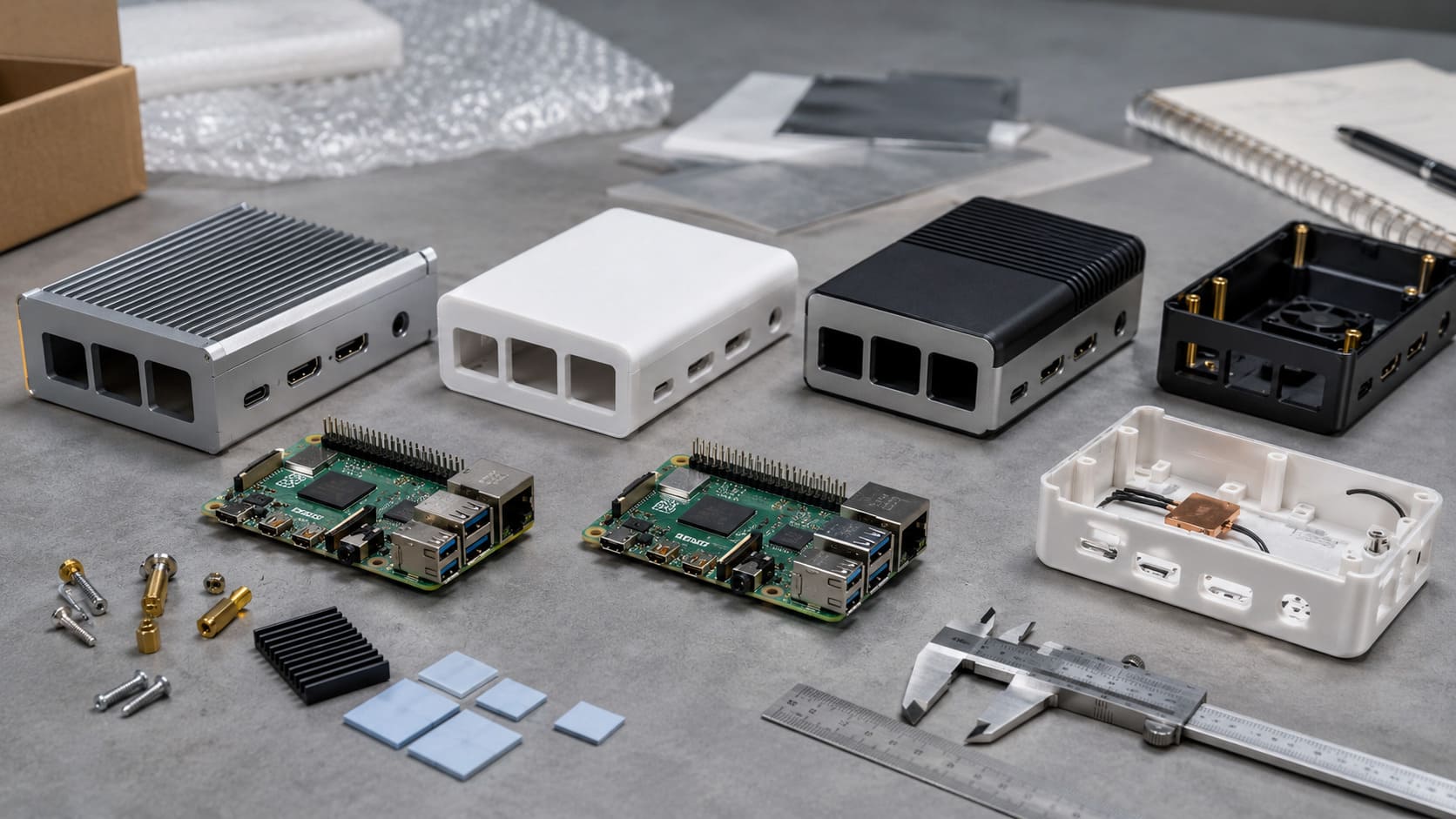
Every new board tells a different kind of story. With the Raspberry Pi 5, it starts with the layout — tighter, sharper, more intentional. As I was inspecting a batch of them on our MaidaTech worktable, I noticed something that made me pause: the port arrangement wasn’t just upgraded — it was designed for integration. That’s when it hit me. This isn’t just a hobbyist tool anymore. It’s a solid, production‑ready core for people who build real products.
What is the Raspberry Pi 5?
The Raspberry Pi 5 is the newest mainline single‑board computer from the Raspberry Pi Foundation. It uses a 64‑bit quad‑core Arm Cortex‑A76 CPU running up to 2.4 GHz and an upgraded VideoCore VII GPU. It can support multiple displays, faster networking, and modern PCIe interfaces.
Why Understanding the Raspberry Pi 5 Schematic Matters
You might wonder why a schematic matters if you are just selling cases and accessories. Here’s the truth: a good schematic gives you a map of how power, signals, and connectors are wired. When you design a case with fans, mounts, or custom panels, knowing these details helps avoid mistakes that could cost you time and money.
Knowing how the power comes in, how the GPIO pins behave, or how PCIe lanes are routed adds confidence when you design a product that integrates with Pi 5. It’s practical knowledge that can save a lot of redesign cycles.
Limitations: Official Schematic Availability (Note for Designers)
Unlike past models, the full official schematic for Raspberry Pi 5 is not publicly released yet. The Raspberry Pi Foundation publishes mechanical drawings and some product briefs, but many electrical details remain hidden.
Community members and engineers on forums confirm this, and often the discussion turns to partial drawings or reverse engineering instead of official releases.
Let’s take a closer look at what you can still learn from the Pi 5’s architecture.
Raspberry Pi 5 Architecture Overview

I like to think of the Raspberry Pi 5 as a tiny city of components. Every part has its role, and all those pieces must work together smoothly. Understanding the big picture helps you make better designs with fewer surprises.
Core SoC: Broadcom BCM2712 and RP1 I/O Controller
At the heart is the Broadcom BCM2712 SoC with the Arm CPU and GPU inside, and the RP1 I/O controller handling USB, networking, and more. This combo makes the Pi 5 faster and more capable than its predecessors.
Memory Subsystem (LPDDR4x)
The Pi 5 uses LPDDR4x memory, which is fast and efficient. This memory sits close to the SoC to reduce latency. As a designer, low latency means better performance for real‑time tasks.
GPU and Multimedia Blocks
The VideoCore VII GPU gives the Pi 5 the ability to handle dual 4K displays and hardware video acceleration. It’s one reason this board is used in kiosks, digital signage, and AI applications.
I/O and Interfaces
The Pi 5 has:
- Dual HDMI outputs
- USB 3.0 ports
- Gigabit Ethernet
- PCIe 2.0 lanes
- Camera and display interfaces
All these connections make the board a flexible platform.
When I first designed a custom enclosure, I had to ensure every port aligned perfectly. A clear understanding of the board’s interfaces saved me hours of trial and error.
Now that you see the layout of the Pi 5’s architecture, let’s explore how power gets into this little machine.
Power System Schematic Overview

Power is one of those things you don’t think about until something goes wrong. I still remember a 고객 support call where a client used a poor‑quality cable and ended up with unstable behavior. Let’s get these basics right.
USB‑C Power Input and PMIC Design
The Pi 5 uses a USB‑C power input because it needs more current than older models. At least a quality 5 V/5 A supply is recommended. A power management IC (PMIC) ensures the board gets stable voltages.
Power Rails and Voltage Regulators
Inside the board, there are several voltage regulators for the CPU, memory, and I/O. While we don’t have the exact official schematic, we know these regulators create stable rails for each subsystem.
Example: Power Rails (Simplified)
| Rail | Purpose |
|---|---|
| 5 V | Main input from USB‑C |
| 3.3 V | Logic and GPIO |
| 1.8 V | Memory interface |
Without clear power routing, sensitive parts can misbehave or overheat.
On/Off Power Button and Real‑Time Clock (RTC) Power
The Pi 5 adds a physical power button, a big comfort for many users. It also supports a small battery for RTC, which keeps time between boots.
Power Sequence and Safety Considerations
When you press power, the sequence in which the rails come up affects stability. A poorly timed sequence can lead to brownouts or resets. This matters when you design cases with power switches or panels.
If your products will integrate external power sources, understanding this sequence can prevent costly errors.
Hope you’re still with me! Let’s walk deeper into the Pi 5’s processor and core logic next.
Processor and Core Logic Block Overview

The brains of the Raspberry Pi 5 can feel a bit mysterious. Let me explain it like this: it’s like a well‑orchestrated team. When every role is clear, you can design around it confidently.
Quad‑Core Cortex‑A76 CPU and Memory Controller
The Cortex‑A76 CPU handles most of the computing tasks. It also talks to memory through a dedicated controller. This design boosts performance for heavier loads.
Southbridge / I/O Controller (RP1)
The RP1 handles most I/O traffic: USB, Ethernet, PCIe‑related signals, and more. It’s like a traffic cop making sure data flows where it should.
GPU Block (VideoCore VII)
The GPU takes care of graphics and video. If you’re building a display product or kiosk, this block makes the Pi 5 capable of driving high‑resolution screens.
Clocking and Reset Circuits
Clock signals keep every digital part in sync. Reset circuits ensure everything starts cleanly when the board powers up.
Understanding how reset and clock paths work helps when debugging hardware issues down the line.
You’ve seen the inner brain now—next, we’ll look at how Pi 5 talks to the outside world.
Connectivity and Interfaces

I once worked on a custom production board where a missing detail in the HDMI trace caused us a week of delays. Once you know the connectivity story, these issues disappear.
USB, Ethernet & Networking Interfaces
The Pi 5 has multiple USB 3.0 ports and a Gigabit Ethernet port. These interfaces are managed through the I/O controller and supported inside the hardware block.
PCIe Interface
Pi 5 exposes a PCIe 2.0 lane, letting you add high‑speed accessories like NVMe SSDs or AI hats.
HDMI and Display Interfaces
There are two micro HDMI outputs, each capable of 4K displays. These go through dedicated display lanes on the board.
Camera (CSI) and Display (DSI) Interfaces
The Pi 5 uses smaller CSI/DSI connectors compared to previous versions, allowing flexible camera and display setups.
GPIO Header and Expansion Interfaces
The 40‑pin GPIO header gives you access to digital I/O pins. This is where makers and designers spend a lot of time connecting sensors and custom boards.
Now that connectivity makes sense, let’s talk about keeping signals clean and reliable.
Signal Integrity and Board Routing Considerations

When you design a custom board or a carrier, how traces are routed matters as much as what they do.
High‑Speed Signals: PCIe and HDMI
High‑speed signals like PCIe and HDMI need careful routing. Improper routing leads to noise and errors.
Differential Pair Routing
Differential pairs (like USB or HDMI data lines) should be kept close and matched in length for signal quality.
Ground and Power Plane Strategy
Good grounding and solid power planes reduce electromagnetic issues and keep the board stable.
You’ve now got the signal story. Next, we explore physical connectors on the Pi.
External Connectors and Peripheral Integration

If you’ve ever fitted a Pi into a custom enclosure, you know connector alignment is critical.
USB Ports and Ethernet Jack
These must align perfectly to avoid stress on the board or cable.
HDMI Connectors
Micro HDMI connectors require space and clearance inside the case.
GPIO Header (40‑pin) Detailed Look
This header is rich with power, ground, and programmable I/O pins.
Other Board Connectors (Debug, Fan, RTC)
Small connectors like fan headers and debug pins are easy to miss on mechanical drawings—but matter in production.
From connectors, let’s bring this into practical use.
Raspberry Pi 5 Pinout and GPIO Mapping (Tie‑in of Schematic to Usage)

Here’s where schematic knowledge becomes practical. The pinout tells you what each pin is meant for.
Pinout Overview and Schematics Relationship
The schematic (even a simplified one) links pins to physical functions.
Important GPIO Functions for Custom Integrations
GPIOs can be used for PWM, sensors, buttons, LEDs, and more.
Schematics Insight for Custom HAT / Accessories
The more you understand the schematic, the better you can plan a HAT or extension board that works first time.
Now let’s talk about real use cases for this blurry schematic world we live in.
Practical Uses of Schematic Knowledge

Designing Custom Carrier Boards
Carriers can host additional slots or connectors with confidence.
Integrating Raspberry Pi 5 into Products
From kiosks to robotics, schematic insight helps reduce risk.
Debugging and Troubleshooting at Hardware Level
Understanding the hardware map puts you in control when things go wrong.
But what do you do when you don’t have official schematics?
Limitations and Workarounds
Lack of Official Raspberry Pi 5 Schematic Release
As noted earlier, officials haven’t released them yet.
Using Mechanical Drawings and Datasheets Instead
You can still use mechanical drawings and product briefs to design enclosures and mounts.
Reverse Engineering & Community Resources
Some projects reverse engineer boards for educational use, but these aren’t perfect.
Now, you know how schematic knowledge helps every step. Let’s bring this closer to what we do at MaidaTech.
My Business Insight (MaidaTech)
I’ve been building Raspberry Pi cases and accessories for years. I’ve seen how schematic insights help our customers avoid pitfalls. Let me share a few insights.
How Schematic Knowledge Helps Case & Accessory Designers
Knowing where mounted components sit helps us design rugged cases that fit precisely and reduce strain on ports.
OEM/ODM Opportunities with Raspberry Pi 5 Hardware Integration
Customers come to us when they need custom mounting, power cut‑outs, or PCIe access in their case designs.
Supporting Custom Power, Cooling & I/O in Case Designs
We help integrate fans, heatsinks, and connectors into your custom case. Our team understands the Pi board layout and uses this knowledge to make your product fit flawlessly.
You’re almost at the end—but let’s wrap this up with a clear conclusion.
Conclusion
Summary of Key Schematic Takeaways
Even without full official schematics, you can still learn how Pi 5’s architecture, power system, and connectors work together.
Where to Find More Detailed Documentation
Keep an eye on Raspberry Pi official docs for updates, mechanical drawings, and community resources.
Final Notes for Engineers and B2B Buyers
If you are designing cases, custom boards, or products around Raspberry Pi 5, schematic insight gives you confidence and reduces rework.